Basic Logic Gates
Basic logic gates explained and all the different ways they can be drawn and represented.
~8min
In electronics, a logic gate is an idealized or physical device implementing a Boolean function; that is, it performs a logical operation on one or more binary inputs, and produces a single binary output.
~10min
Key Terms:
Logic Gates, NOT/AND/NAND/OR/NOR/XOR/XNOR
MOSFET = Metal–Oxide–Semiconductor Field-Effect Transistor (MOSFET, MOS-FET, or MOS FET)
NMOS and PMOS = MOS integrated circuits
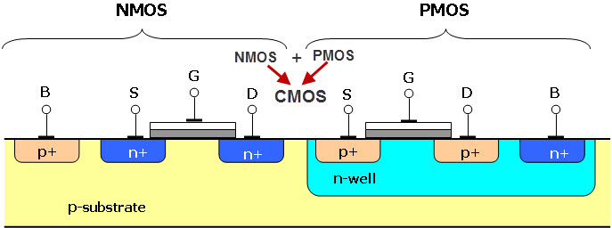
Bonus: CMOS Technology
CMOS = Complementary and symmetrical pairs of p-type and n-type metal oxide semiconductor field effect transistors (MOSFETs) for logic functions.
A CMOS inverter has a PMOS and an NMOS transistor that is connected at the gate and drain terminals, a voltage supply VDD at the PMOS source terminal, and a GND(ground) connected at the NMOS source terminal, where Vin is connected to the gate terminals and Vout is connected to the drain terminals.
Used in digital logic circuits, microprocessors, microcontrollers and static RAM.